Coulee Region Fieros
Serving Fiero lovers in the La Crosse and Eau Claire areas.
The Picture Book of the ALDL Cable
Ever wish that your computer could talk?
These cables are not hard to make. You do need some soldering experience and patience. You will also need software to make your home computer talk to your Fiero computer. You can find the software at http://www.winaldl.webhop.net/ . Please look at this site for the wiring diagram before you start this project.
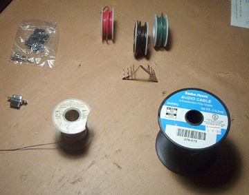
Supplies:
3 10k resistors
1 DB-9 serial connector (female)
At least 3 feet of wire
1 NPN switching transistor
1 DB-9 connector hood
Solder
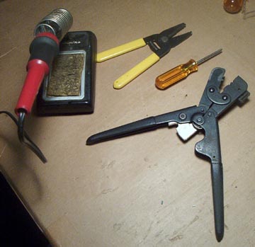
Tools:
Soldering iron
Wire Stripers
Phillips head screwdriver (small)
I will let the pictures do most of the talking.
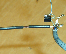
To start with you need a 3 - 15 foot 2 conductor wire. One the first one that I made I just bought a three pack of wire at Radio Shack and braded them together. It wasn't the cleanest look, but it worked and saved money.
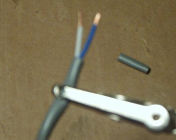
Sorry it is fuzzy I had some trouble with the macro function. The jacket is removed and about an inch of wire is exposed. Now you need to strip the individual wires between 1/6th and 1/8th of an inch.
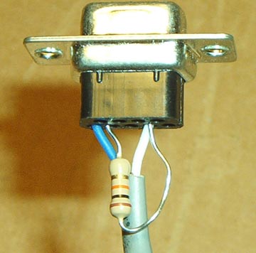
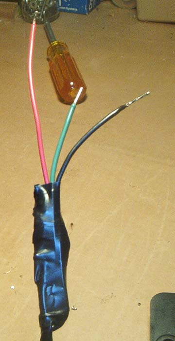
Now this is the tricky part. I am using crimp style ends if you are soldering just solder the ends in as you see in the picture. Notice that the connector is upside down in the picture (the shorter row is facing you) All the wires get connected to the long row. Note the numbers on the back of the female DB-9 connector. The ground goes in hole 5. one resistor end goes in hole 4 alone and the other gets connected to hole 2 with the positive lead. If it would be easier for you, you can solder the resistor in hole 2 and then solder the positive lead to the resistor. The resistor lead going into hole 4 has been cut in half.
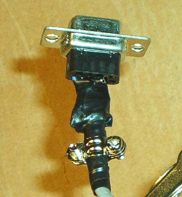
Now cover everything with electrical tape so that it cannot short out. The Bracket has also been installed that comes with the DB-9 connector. This gives the wire some pull strength and should be located inside of the hood. However, if you are careful with the wire you can skip this step. Now install the hood. There should be 6 screws. The two short ones go into the bracket. Then there are 2 that are only half threaded. This go through the hood and DB-9 connector. I'd skip these, they are in place so that you can screw the connector into the back of the computer. I haven't had any problems with my connectors pulling out. Finally there are two long screws that go through the hood to hold it together. What I do is hold the little nut on the under side of the hood with the pointer finger of my left hand and put the screw through the hood, then take the screw driver in my right hand and screw the screw through the nut until it is very snug. Now the connector for the computer is together and it is time to put the end for the car computer together.
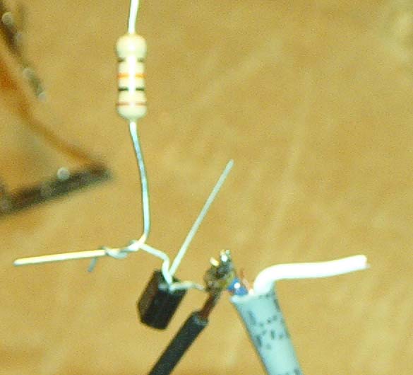
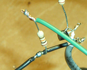
Again strip off the jacket to expose about 1 inch of wire. Strip the wire 1/8th to 3/16th of an inch. Solder the Blue wire to the black wire to the transistor. If you are using different colored wire, you want the wire that is pinned into the number 5 port on the 9 pin connector. Transistors can vary so you need to look at the package and make sure that this is all soldered to the emitter side of the transistor.
Now you need to solder a 10k resister to the Base side of the transistor. On my transistors it happened to be the middle one. Finally solder the positive, or the wire that connects to the two pin to the collector side of the transistor. Remember to check the package to find out which leads are which on your specific transistor.
Now solder a wire to the end of the resistor that you soldered to the base side of the transistor.
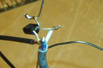
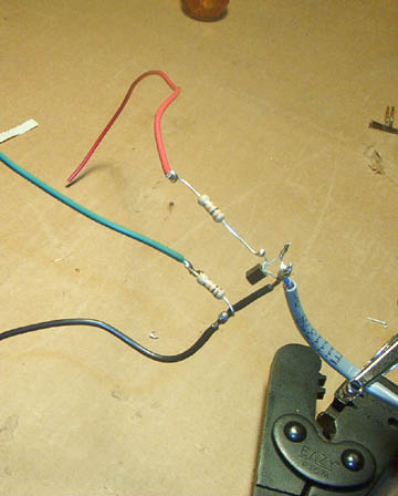
Now you need to strip the black wire that you soldered to the base side of the transistor. Carefully cut the insulation and push it away from the solder joint. leaving a stripped area of wire towards the solder joint.
Now wrap one lead from a 10k resistor around the stripped wire. Solder the resistor in place. Solder another piece of wire to the other resistor. Almost done hang in there.
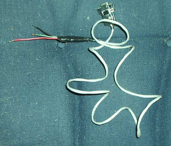
Now all your wires are in place. It is time to wrap with electrical tape.
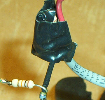
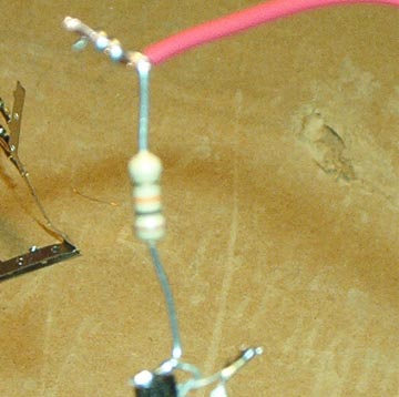
Make sure that you tape them in such a way that it does not short out. Also in the picture above you can see that I tinned the ends. That makes it possible to push the wires into the ALDL connector. I generally strip and tin 1/2 inch.
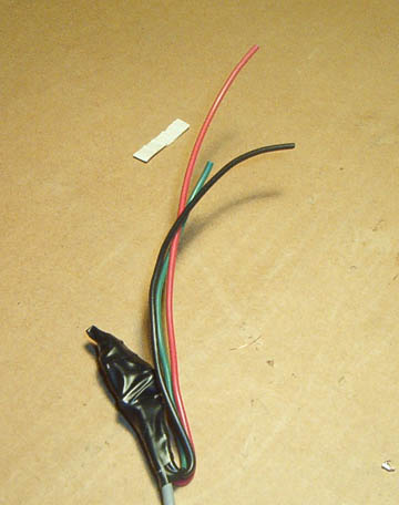
This is what you will end up with. Yup the chair is dirty, but I have 2 dogs and a cat. Now to plug it into the car. The connector can only go into the computer one way so that is the easy part. In the ALDL connector, find the row ( horizontal ) with three pins in it. The two pins right next to each other on the passenger side get the black and green wires. The black wire goes in the pin closest to the passenger side. The green wire goes in the one right next to it. The green wire is only need on the 86+ Fieros. The red wire goes in the only pin left in the row. Be careful not to plug it in to the fuel pump test port. The test port is in the top row all by itself. Turn on you computer and your car, boot WINALDL and you are ready to go.
This information is used at the owners risk. Coulee Region Fieros or any of its members cannot be held responsible for any damage to yourself or property.